Superheaters. When steam is admitted to the cylinder it meets the cylinder walls, the temperature of which is less than that of the entering steam, and there results an interchange of heat. The fact that the steam gives up a part of its heat to the cylinder, causes some of the steam to condense. As the piston proceeds on its stroke and expansion occurs, some of the steam initially condensed will be re-evaporated. The cylinder, therefore, goes through a process of alternately cooling and reheating, resulting in condensation and re-evaporation; this is the principal loss occurring in the process.In order to assist in reducing this loss to a minimum, superheated steam is being used on locomotives, to a certain limited extent in the United States, by the addition of a superheater. A superheater consists of a series of tubes and headers usually placed in the smoke-box, through which steam passes on its way to the cylinders, thus raising its temperature. It has now secured a certain amount of heat energy from the waste gases which pass out of the stack, thus improving the economy of the locomotive.
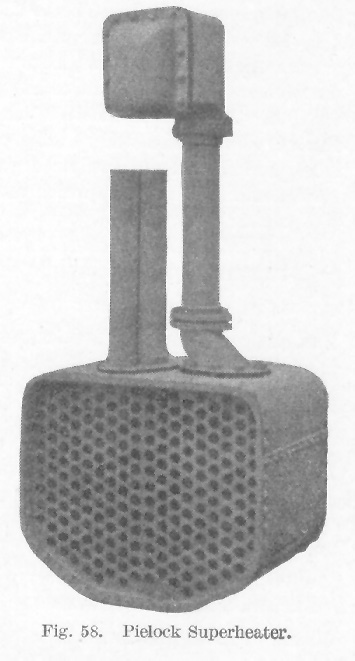
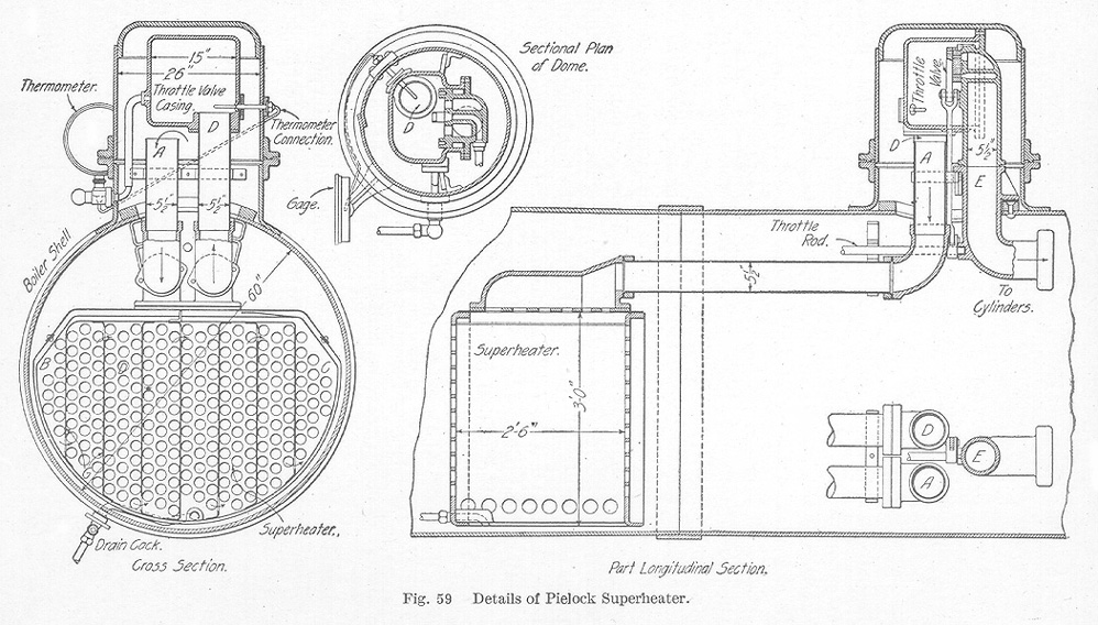
Pielock Superheater. The Pielock superheater, illustrations of which are shown in Fig. 58 and Fig. 59, is found in use on a number of railways in Germany and in Italy, and also on the Hungarian State Railways. Its construction consists of a box containing tube plates corresponding to those of the boiler, the box being set in the boiler barrel so that the flues pass through it. It is placed at such a distance from the fire-box as will prevent the tubes from becoming overheated. The vertical baffle plates G between the rows of tubes cause the steam to follow a circuitous path passing up and down between the tubes. The steam from the dome passes down the open pipe A, Fig. 59, to the left-hand chamber B, then transversely to the several chambers as shown by arrows until it reaches the right-hand chamber C. From the chamber C it passes up through the pipe D to the chamber enclosing a throttle valve from which it enters the steam pipe E.
In installing the superheater, the boiler tubes are first set in place in the superheater and then placed in the boiler, the smoke-box tube plate being left off for this purpose. The tubes are first expanded into the fire-box or back flue-sheet, then in the superheater plates (for which a special mandrel is used), and finally in the front flue-sheet. A blow-off cock extends from the bottom of the superheater through the boiler by means of which any leaks in the superheater may be detected. A gauge at the bottom indicates the degree of superheat of the steam in the throttle valve chamber.
This type of superheater can be applied to a locomotive without making any alteration since the superheater is built to fit the boiler in which it is to be used. It does not interfere with the cleaning of the flues or the washing out of the boiler. It is reported that by the use of this superheater a saving in coal of about 15 to 18 per cent and in water of about 20 per cent, is effected.
Schmidt Superheater. The Schmidt superheater is another type which is largely used on German railroads. Its construction is based on entirely different principles from those of the Pielock superheater. It differs from the Schenectady or Cole superheater in details only.
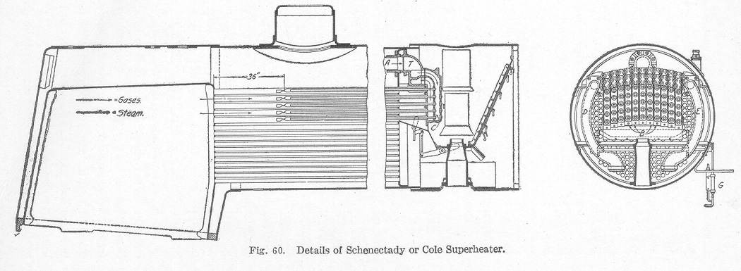
Schenectady or Cole Superheater. The Schenectady superheater was developed by the American Locomotive Company. It has had a large application in recent years and good results are being obtained. The general arrangement and construction of this superheater is shown in Fig. 60 and Fig. 61.
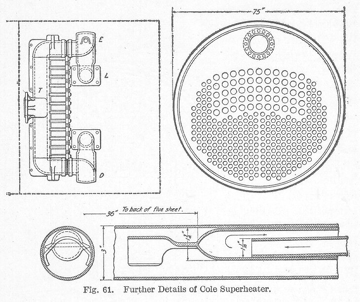
The use of bent tubes and the necessity for dismantling the whole apparatus in order to repair a single leaky boiler tube gave rise to many objections to the use of superheaters. In the construction of the Schenectady superheater, many of the objectionable features have been eliminated. By reference to Fig. 60, it will be seen that steam entering the T-pipe from the dry pipe A is admitted to the upper compartment only. To the front side of the T-pipe are attached a number of header castings B, the joint being made with copper wire gaskets, as in steam chest practice. Each header casting is subdivided into two compartments by a vertical partition shown in cross-section at C. Five tubes each l 1/16 inch outside diameter are inserted through holes (subsequently closed by plugs) in the front wall of each header casting. These tubes having first been expanded, special plugs are firmly screwed into the vertical partition wall and are enclosed by five 1¾-inch tubes which are expanded into the rear wall of the header casting in the usual way. Each nest of two tubes is encased by a regular 3-inch boiler tube which is expanded into the front and back tube sheets as usual. The back end of each inner tube is left open and the back end of each middle tube is closed. The back ends of the two tubes are located about 36 inches forward from the rear flue sheet. The arrangement of the three flues is shown In Fig. 61. The inner tube is allowed to drop and rest on the bottom of the middle tube while the end of the middle tube is so constructed as to support both the inner and middle tubes in the upper part of the 3-inch tube, thus leaving a clear space below.
As can be seen from Fig. 60, steam from the dry pipe enters the forward compartments of each of the header castings, passes back through each of the inner tubes, thence forward through the annular space between the inner and middle tubes, through the rear compartments of each of the header castings, and thence into the lower compartment of the T-pipe, thence by the right and left steam pipe D and E to the cylinders. The steam in passing through the different channels is superheated by the smoke-box gases and products of combustion. In this particular design, fifty-five 3-inch tubes are employed, thus displacing as many of the regular smaller tubes as would occupy a similar space.
It is necessary to provide some means by which the superheater tubes shall be protected from excessive heat when steam is not being passed through them. In this instance, this is accomplished by the automatic damper shown in Fig. 60. The entire portion of the smoke-box below the T-pipe and back of the header castings is completely enclosed by metal plates. The lower part of this enclosed box is provided with a damper which is automatic in its action. Whenever the throttle is opened and steam is admitted to the steam chest, the piston of the automatic damper cylinder G is forced upward and the damper is held open, but when the throttle is closed, the spring immediately back of the automatic damper cylinder closes the damper and no heat can be drawn through the 3-inch tubes. In this way, the superheater tubes are prevented from being burned. There is a slight loss of heating surface in introducing the group of 3-inch tubes and applying a superheater, but this loss is more than offset by the gain in economy due to the use of the superheated steam.
The results of laboratory tests of the Schenectady superheater indicate a saving of from 14 to 20 per cent of water and from 5 to 12 per cent of coal.
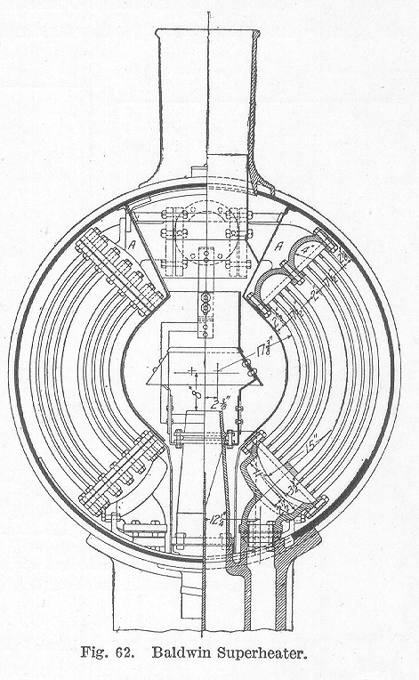
Baldwin Superheater. The Baldwin superheater which is now being used by some railroads differs from the Schenectady and the Pielock superheaters in that it is found entirely within the smoke-box. It can be applied to any locomotive without disturbing the boiler and its application does not reduce the original heating surface.
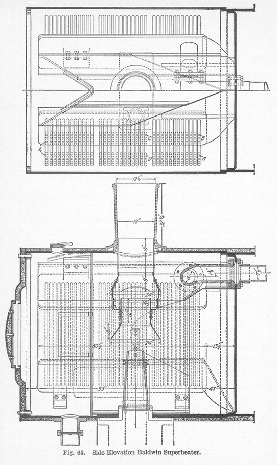
It consists of two cast-steel headers A, Fig. 62, which are cored with proper passages and walls. These headers are connected by a large number of curved tubes which follow the contour of the smoke-box shell, and are expanded in tube plates bolted to the headers. The curved tubes are divided into groups, the passages in the headers being so arranged that the steam after leaving the T-head on either side passes down through the group forming the outer four rows of the rear section of superheater tubes, then crosses over in the lower header and passes up through the inner group of the next section and up through the outer group and thence down through both the inner and outer groups of the forward section and through a passage-way in the lower header to the saddle. As illustrated in Fig. 63, these tubes are heated by the gases from the fire tubes and the deflecting plates are so arranged as to compel these gases to circulate around the tubes on both sides to the front end of the smoke-box and thence back through the center to the stack. Thus, the superheater uses only such heat as is ordinarily wasted through the stack, and whatever gain in superheat is obtained, is clear gain.
Experiments so far made with this type of superheater show that while it is not possible to obtain a very high degree of superheat, yet enough is obtained to very decidedly increase the economy of the boiler. The front end is heavily lagged at all points to prevent as far as possible all loss of heat by radiation.
There have been several types of superheaters placed on the market in addition to those already mentioned, all having more or less merit. They differ in detail of construction but the principle embodied is covered by some one of the types described in the preceding pages.
Superheater Tests. Of recent years much experimental work has been done to ascertain the relative increase in economy obtained by the use of locomotives equipped with superheaters and to determine the increase, if any, in the maintenance of locomotives so equipped. In many instances the published data on the subJect is presented in such a manner as to make comparisons rather difficult. The experiments conducted by Dr. Goss during the last few years have been of much interest to railroad men. The work was conducted on the Purdue locomotive, having a boiler designed to carry a working pressure of 250 pounds per square inch. The results obtained are very briefly summarized in Tables IV, V, VI, and VII.
TABLE IV
Steam per Indicated Horsepower per Hour
(Cole Superheater)
Boiler Pressure in Pounds per Sq. In. Gage Superheat in Degrees F. Pounds Steam per I.H.P. per Hour Saturated Steam Pounds Steam per I.H.P. per Hour Superheated Steam Saving in Per Cent by Use of Superheated Steam 240 139.6 24.7 22.6 8.50 220 145.0 25.1 21.8 13.14 200 150.3 25.5 21.6 14.51 180 155.6 26.0 21.9 15.77 160 160.8 26.6 22.3 16.16 140 166.1 27.7 22.9 17.32 120 171.4 29.1 23.8 18.21 TABLE V
Coal per Indicated Horsepower per Hour
(Cole Superheater)
Boiler Pressure in Pounds per Sq. In. Gage Pounds Dry Coal per I.H.P. per Hour Saturated Steam Pounds Steam per I.H.P. per Hour Superheated Steam Saving in Per Cent by Use of Superheated Steam 240 3.31 3.12 5.74 220 3.37 3.00 10.98 200 3.43 2.97 13.41 180 3.50 3.01 14.00 160 3.59 3.08 14.21 140 3.77 3.17 19.51 120 4.00 3.31 17.27 TABLE VI
Steam per Indicated Horsepower per Hour
(Schmidt Superheater)*Results estimated for making comparisons.
Boiler Pressure in Pounds per Sq. In. Gage Superheat in Degrees F. Pounds Steam per I.H.P. per Hour Saturated Steam Pounds Steam per I.H.P. per Hour Superheated Steam Saving in Per Cent by Use of Superheated Steam 240 222.2* 24.7 19.5* 21.05 220 226.5* 25.1 19.0* 24.30 200 230.8 25.5 18.9 25.89 180 235.1 26.0 18.7 28.08 160 239.4 26.6 18.9 28.94 140 243.8 27.7 19.5 29.60 120 248.6 29.1 21.0 27.83
TABLE VII
Coal per Indicated Horsepower per Hour
(Schmidt Superheater)*Results estimated for making comparisons.
Boiler Pressure in Pounds per Sq. In. Gage Pounds Dry Coal per I.H.P. per Hour Saturated Steam Pounds Steam per I.H.P. per Hour Superheated Steam Saving in Per Cent by Use of Superheated Steam 240 3.31 2.63* 20.54 220 3.37 2.57* 23.74 200 3.43 2.55 25.65 180 3.50 2.51 28.28 160 3.59 2.55 28.97 140 3.77 2.63 30.24 120 4.00 2.89 27.75 The results presented in Tables IV to VII were all obtained at a uniform speed of 30 miles per hour, and may be briefly stated as follows:
(a)With the locomotive equipped with a Cole superheater a saving was effected, over values obtained with saturated steam, in steam used per I.H.P. per hour of from 8.5 to 18.21 per cent and in coal per I.H.P. per hour of from 5.74 to 17.25 per cent.
(b)With the locomotive equipped with a Schmidt superheater the saving of steam used per I.H.P. per hour varied from 21.05 to 29.60 per cent, while the saving in coal used per I.H.P. per hour varied from 20.54 to 30.24 per cent.
(c) The superheat in the branch pipe just before entering the cylinders, varied from 139.7 to 171.4 degrees F., when the Cole superheater was used, and from 222.2 to 248.6 degrees F., when the Schmidt superheater was used,
The higher efficiency obtained of the Schmidt superheater over the Cole superheater is partially accounted for by the fact that the total heating surface of the Schmidt amounted to 325 square feet, while that of the Cole was only 193 square feet.
In conclusion, it may be stated that the superheating simple locomotive will reduce the steam and coal consumption to that required by the compound locomotive. It will operate efficiently on comparatively low steam pressures, and its maximum possible power is considerably beyond that of the simple locomotive using saturated steam. Many complaints have been made by operators relative to difficulty experienced in securing proper lubrication of the valve, etc., when using superheated steam. It has been demonstrated, however, that this difficulty can be overcome by the exercise of good judgment in the use of and proper amount and grade of lubricating oil.
Table of Contents; Page 63; Page 74; Index
