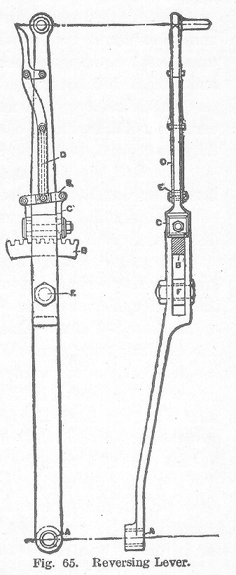
Stephenson Valve Gear. The Stephenson gear consists of the reverse lever, reach rod, lifting shaft, link hanger, link, eccentric, and rocker arm.The reversing lever is given a variety of forms, a good design of which is illustrated in Fig. 65. The lever is pivoted at A, below the floor of the cab and can be moved back and forth beside the quadrant B to which it can be locked by means of the latch C. This latch is held down by a spring surrounding the rod D, acting on the center of the equalizer E. This makes it possible to use very fine graduations of the quadrant and by making the latch as shown, the cut-off can be regulated by practically what amounts to hal^notches.
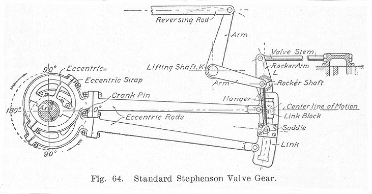
The reach rod, or reversing rod, is fastened to the reversing lever at F and consists of a simple piece of flat iron having a jaw at one end by which it serves to connect the reversing lever and the lifting shaft K, shown in Fig. 64.
The lifting shaft, shown at K, Fig. 64, consists of a shaft held in brackets usually bolted to the engine frames to which are connected three arms, one being vertical and to which is attached the reach rod, and two horizontal ones from which the links are suspended.
The link hanger is a flat bar with a boss on each end. It carries the link by means of a pin attached to the link saddle, illustrated in Fig. 64.
The link, Fig. 64, is an open device held by the saddle and fitted with connections for the eccentric rod.
The eccentrics, Fig. 64, usually of cast iron, are fitted to the main driving axle.
The rocker arm, Fig. 64, consists of a shaft to which two arms are connected, the lower one of which is attached to the link block and the upper to the valve stem.
Setting the Valves. This is a comparatively simple operation but one requiring great care. On account of the angularity of the rods, it is impossible to adjust any link motion to give equal cut-off at all points for both strokes of the piston. The most satisfactory arrangement is one which provides for an equalization of the lead and cut-off at mid-gear. But even this will cause a variation of cut-off of from 3/8 to 1/2 of one per cent in the full gear part of the cut-off and at other points.
In setting the valves upon a locomotive, some means must be employed for turning the main driving wheels. This is usually accomplished by mounting the main drivers upon small rollers which can be turned by a ratchet or motor without moving the locomotive as a whole. If a set of rollers are not available, the locomotive may be moved to and fro by using pinch bars.
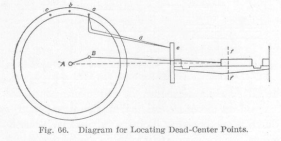
Before undertaking the setting of the valves, the length of the valve rod must be adjusted. To do this, set the upper rocker arm vertical if the valve seat is horizontal; if inclined, the rocker arm must be placed perpendicular to the plane of the valve seat. Next adjust the length of the valve rod so that it will connect with the rocker arm and the valve when the valve is in its central position. The next step is to locate the dead center points which points give the position of the crank on the dead center. It is very essential that this be done very accurately since a small movement of the crank at this position moves the piston but very little while the same movement causes a comparatively large movement of the valve. Hence, if the dead center points are not accurately located, the valves will not be set so accurately as they otherwise would be. To locate the dead center points, proceed as follows: First, secure a tram d as shown in Fig. 66. This tram should be made of a steel rod about 1/4 inch in diameter having each end pointed, hardened, and tempered so as to retain a sharp point. With a center punch, make a center e on some fixed portion of the frame in such a position that when one point of the tram is in the center e, the other pointed end can be made to describe lines on the main driver. To locate the forward dead center, turn the driver ahead until the crank has almost reached the center line as shown in the position A B, Fig. 66; that is, when the crosshead is, say, 1/2 inch from the extreme point of its travel. With the parts in this position, place the tram point in e as shown and locate the point a on the driver, and describe the line ff on the crosshead and guide. Next turn the driver ahead until the crank passes the dead center and the lines ff again coincide, when a second point c is marked by means, of the tram at the same distance from the center of the axle as the point a. With a pair of dividers locate the midposition b between a and c. In setting the valves for the head end, the required dead center will be located when one tram point is in the center e and the other in the center b. The dead-center point for the back stroke is located in the same manner as just described. An attempt to place the engine on dead center by measurements taken on the crosshead alone would likely result in an error, since the crank might move through an appreciable angle while passing the dead center and the consequent movement of the crosshead be inappreciable, hence the advisability of using the more exact method explained above is made apparent.
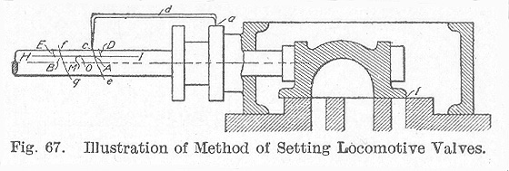
The reverse lever and all the parts having been connected, to set the valves for forward gear, the procedure is as follows: Place the reverse lever in its extreme forward position. When this is done turn the engine ahead until the valve is just beginning to cut off, as shown at l, Fig. 67. When this point is reached, stop the engine and make a small punch mark such as a on the cylinder casting. Then put one end of the tram b into the punch mark and describe an arc c e on the valve stem. Next turn the driver ahead until the valve is just cutting off on the other end. With the same center a as used before, describe another arc f g on the valve stem. These two arcs are known as the port lines and are to be the reference lines for the work which follows. Draw a straight horizontal line H I on the valve stem and where it intersects the arcs, make the center marks A B. The center A is the front port mark and the center B the back port mark. Next, place the reverse lever in the extreme backward position and locate points on the valve stem similar to the points A and B.
To avoid confusion, it is better to make all tram marks for the forward movement above the line H I and all those for the backward motion below.
In trying the forward movement of the valve, see that the reverse lever is in the extreme forward position, then by running the engine ahead, place the crank in turn on each dead center, and describe an arc on the valve stem. In trying the valve for the backward gear, place the reverse lever in its extreme back position and by running the engine backward, place the crank on each dead center and describe arcs on the valve stem as before. In either case, if the dead center is past, do not back up to it but either make another revolution of the engine or back beyond it some distance, then approach it from the proper direction. This must be done in order to eliminate all lost motion.
These trial tram lines should be compared with the port marks when the engine is placed in the forward and backward gear.
If the trial tram lines fall outside of the port marks, so much lead is indicated, while if they fall within the port marks, so much negative lead is indicated.
It is customary for railroad companies to set the valves on their locomotives to give equal lead. The method commonly employed is presented herewith. Having the reverse lever in the extreme forward notch, run the engine ahead, stopping it on the forward dead center. With the tram b in the center a, Fig. 67, describe the arc D above the line H I. Next turn the engine ahead until the back dead center is reached; using the tram b again with a center at a, describe the arc E above the line H I. With dividers, find a mid-point 0 between E and D. If the center 0 is ahead of the point M, which is midway between the port marks A and B, the eccentric blades which control the forward motion must be shortened an amount equal to the distance between M and 0. When this is done, the lead will be equalized. If it is desired to increase the lead, move the forward eccentric toward the crank. To decrease the lead, move the forward eccentric away from the crank. After all of these changes have been made, repeat the operation in order to check the results. If this does not give the desired results, correct the error by repeating the process and continue by trial until the conditions sought for are obtained.
To set the valves for the back motion, proceed in the same manner as that described for the forward motion, all the changes being made on the eccentric blades and eccentric which control the backward motion.
In all that has been said regarding the setting of the Stephenson valve gear, it is assumed that the gear is one having open rods; that is, one in which the rods are open, not crossed when the eccentrics face the link.
Table of Contents; Page 84; Page 89; Index
