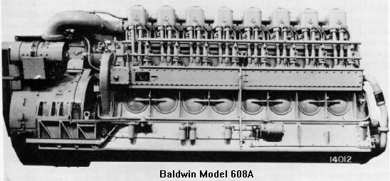
Baldwin 608A Diesel Engine
| Bore | Stroke | Cyl. Disp | Rated RPM | Cyl. scavenging |
|---|---|---|---|---|
| 12.75" | 15.5" | 1979 cu. in. | 625 | Turbocharger |
| Bore | Stroke | Cyl. Disp | Rated RPM | Cyl. scavenging |
|---|---|---|---|---|
| 12.75" | 15.5" | 1979 cu. in. | 625 | Turbocharger |
The following is from a Baldwin-Lima-Hamilton specification manual.Bedplate: Welded steel structure, with four-point mounting to the locomotive underframe, extending the length of the engine, with reinforced extensions for supporting main generator. Serves as a reservoir for engine lubricating oil. Heavy cast steel transverse webs support main bearings. Main bearing bores precision machined. Engine mounting bolts at generator end fitted with hollow dowels serve as shear blocks.
Frame: Welded, carbon molybdenum steel structure which forms the cylinder housing and upper part of the crankcase. Neoprene seats used throughout.
Crankshaft: Heat-treated, steel forging drilled for pressure lubrication of all bearings. Shaft is counterweighted and dynamically balanced. Coupling flange for bolting crankshaft to generator is integral with the shaft.
Bearings-Main & Crankpin: Thin shell, heavy-duty, copper lead, strip type, fitted to bedplate. Removable through crankcase openings without disturbing crankshaft.
Cylinder Liners: Alloy cast iron, porous chrome-plated for wear resistance. Flanged upper end fits into frame counterbore, lower end provided with rubber sealing rings between liner and frame. This arrangement permits expansion and contraction of liner due to thermal changes.
Pistons: Heat-treated alluminum alloy, cooled by a continuous flow of oil passing through steel coils cast into piston crown. Provided with four taper-faced and twisted compression rings, and three oil control rings.
Connecting Rod: Drop forged, heat-treated alloy steel, with interchangeable bearing shells. Connecting rod bolts are heat-treated alloy steel. Bronze wristpin bushing. Rods are drilled for pressure lubrication of wristpin bearings and are held within specified weight tolerances for improved engine balance.
Cylinder Heads: Annealed high grade iron, attached to frame by six heat-treated alloy steel studs. Each head provided with two exhaust and two intake valves, with fuel injector located in the center. Valves and actuating mechanisms enclosed by removable aluminum covers.
Valves: Exhaust and intake valves (two each) are heat-treated alloy steel. Each valve is provided with two alloy steel springs concentrically arranged. Valves are actuated by rocker arms mounted on brackets attached to the cylinder heads. Rocker arms are actuated by hollow push rods socket-mounted in cam followers with solid, full floating, bronze bushings and hardened steel rollers and pins, pressure lubricated. Valves, rocker arms and push rods are lubricated from the engine pressure system.
Camshaft: Camshaft, with integral cams, consists of two sections bolted together, with each section removable. Supported in split-type removable bearing shells, it is driven by a roller type chain.
Governor: Electro-Hydraulic, variable speed, isochronous type (maintains same average engine speed, regardless of load), gear-driven from camshaft and electrically operated by throttle. Maintains desired engine speed by controlling quantity of fuel delivered by the injection pumps. Governor incorporates load regulator and low lube oil shut down device.
Overspeed Stop: Centrifugal trip type, gear-driven from the crankshaft. Shuts down engine when engine speed exceeds predetermined maximum speed setting.
Fuel System: Solid injection type with spring loaded, multi-hole spray nozzles and individual pump for each cylinder. Fuel oil is supplied to the pumps by motor-driven fuel supply pump. Strainer is provided in suction line between tank and supply pump, cartridge type filter is located in pressure line between supply pump and injection pumps. A shut-off valve, manually operated from either the inside or outside of locomotive is supplied in the suction line to the supply pump. A fuel injection pump relief valve and a fuel supply pump discharge relief valve are provided.
Lubricating Oil System: A positive displacement gear pump, chain-driven from the crankshaft, draws lubricating oil from the engine base and circulates it through the system. The oil passes through a suction strainer before entering the pump, then through proper filters and a heat exchanger before delivery to the engine parts. An engine shut-down device incorporated in governor will stop the engine if the lubricating oil pressure drops below a predetermined setting. Pressure relief valves are provided for heat exchanger, lube oil pumps and filters.
Cooling Water System: An engine mounted, chain-driven, centrifugal pump of Baldwin design circulates water through the engine, radiator and heat exchanger. Water temperature is thermostatically controlled.
Supercharger: Exhaust gas turbine and centrifugal blower mounted on a common shaft. The exhaust gas turbine utilizes energy in exhaust gases to drive the centrifugal blower which furnishes air to engine through an air intake manifold. Supercharger assures full engine power up to 8,000 ft. altitude.
Oil Bath Air Filter & Silencer: Combination oil bath air filter and silencer consisting of two filtering elements mounted on a manifold flexibly connected to the engine.
Air Intake Manifold: Reinforced welded steel structure directs supercharged intake air to cylinders.
Exhaust Manifold: Welded steel tubing, insulated, conducts exhaust gas from cylinder to supercharger.
Crankcase Ventilation: Provided by slight negative pressure created by a venturi connected to the air intake manifold. Oil vapors are discharged to atmosphere. Oil condensed in separator is trapped for return to the crankcase.
